SPI Modes

SPI knows 4 "standard" modes, reflecting the SCK's polarity (CPOL) and the SCK's phase (CPHA).

SPI Mode CPOL CPHA
0 (or 0,0) 0 0
1 (or 0,1) 0 1
2 (or 1,0) 1 0
3 (or 1,1) 1 1

The meaning is:

CPOL:
  • 0 = Clock Idle low level
  • 1 = Clock Idle high level
CPHA:
  • 0 = SDO transmit edge (*) active to idle
  • 1 = SDO transmit edge idle to active
(*): the transmit edge is the clock edge at which the SDO level changes.

In a timing diagram this looks like(only one clock pulse shown here):


The Transmit edge is the clock edge at which the SPI output data changes,
The Sampling edge is the clock edge at which the sampling of the SPI input data takes place.
The sampling edge is normally the opposite one of the transmit edge.


References: www.rosseeld.be, dlnware.com

Suppress any warning in mbed Compiler

The mbed Compiler is a very usefull development platform for microcontrollers, but sometimes you will get warning messages, some of which you know about and want to be ignored. They appear on the first lines of "Compiler output" and you need to scroll down to reach the "real" compiler errors.

You can suppress specific compiler errors and warnings by using #pragma diag_suppress in the header of your project before any include happens.

#pragma diag_suppress sets a specific warning code or multiple warning codes and the compiler will ignore those warnings.

All the error and warning codes can be found on http://infocenter.arm.com website.

Examples:


alternative link

References: developer.mbed.org/forum/, about diag_suppress tag, ARM compiler warning and error codes,

16 bit color generator (RGB565 color picker)

One of the previous notes was about 16 bits RGB color representationRGB565 format. This note will be based on that note and you will be able to generate any color, within 16 bit color depth, by using the color picker below.

Hexadecimal 24 bit color depth value:

Hexadecimal 16 bit color depth value:

Color picker with preview:
spectrum

C++ array of pointers to objects

I was driving multiple TFT LCDs on the same microcontroller. Each LCD had its own instance and I needed an easy method of iterate through all of them.

The platform I used is a ST Nucleo F411RE board, the programming enviroment is mbed and the TFT LCDs are 2.2 inch ILI9341 display.

By using a single screen, the code could look like this:


On the other hand, by using multiple screens, the code could look like this:


The code is not elegant, but it gets the job done.
Note that the LCDs RST and CS pins need to be individually connected to the microcontroller.

Reference: www.java2s.com

8x8 dot matrix font generator for LCD

This is a javascript based 8x8 pixel font generator for any LCD.

How it works: just click on the dot matrix to enable and disable a dot. On the right side, the equivalent binary code will be generated. The reset button will reset the entire dot matrix. Multiple dot selection is not supported.

 0  0  0  0  0  0  0  0
 0  0  0  0  0  0  0  0
 0  0  0  0  0  0  0  0
 0  0  0  0  0  0  0  0
 0  0  0  0  0  0  0  0
 0  0  0  0  0  0  0  0
 0  0  0  0  0  0  0  0
 0  0  0  0  0  0  0  0

Binary code:


The code for generating "8x8 dot matrix font generator" is taken from www.pial.net.

QVGA 2.2" (240x320) TFT SPI display with SD-CARD pinout

The QVGA 2.2" TFT SPI display was bought from Ebay. The display driver is ILI9341 and the board uses 3.3V logic.
The maximum color depth this TFT supports is 16 bit.
The SD-CARD is powered from the display VCC and has separate SPI pins.

Warning! The QVGA 2.2" TFT does not support 5V on either of its pins.


The TFT display pins:

SDO (MISO)
LED = 3.3V or in series with a 100 ohm resistor from 5V
SCK (CLOCK)
SDI (MOSI)
D/C (DATA/COMMAND)
RESET
CS (CHIPSELECT)
GND
VCC = 3.3V

The SD-CARD pins:
SD_CS (CHIPSELECT)
SD_MOSI (MOSI)
SD_MISO (MISO)
SD_SCK (CLOCK)


References: ILI9341 PDF manual, www.instructables.com

PHP script to transform a 24 bits color depth image into 16 bits color depth raw and back again

Just like the title says, the following script will transform a 24 bits color depth image file into 16 bits color depth raw file. You also have the option to view that raw file.

Alternate link

16 bits RGB color representation

On a screen, each pixel is represented using 16 bits or 2 bytes (1 bytes = 8 bits). Each color has 5 bits allocated to its color depth, but green, which has 6 bits of color depth. This is the RGB565 format.


This can lead to small discrepancies in encoding, when someone wishes to encode the 24-bit color RGB with 16 bits. Green is usually chosen for the extra bit in 16 bits because the human eye has its highest sensitivity for green shades, therefore the discrepancies are harder to see. Note that 16 bits of color utilizes a color palette of 32x64x32 = 65,536 colors.

A few examples of 16 bits colors in C++:

Alternate link

References:
www.willamette.edu/~gorr/, wikipedia.org, learn.adafruit.com

Low voltage RS232/Serial switch

This schematic is useful when you have 2 devices that needs to be controlled by 1 MCU. As it's seen below, the MCU switches between the 2 serial devices. The MCU can only talk with 1 device at a time with both RX/TX channels.


SW1 can also be controlled by the MCU. U1 is 74HC04 or equivalent. U2 is SN74LVC125A or equivalent.

Reference:
WizFi250 Datasheet v1.01
PDF manuals:
Texas Instruments SN74LVC125A, NXP 74HC04

ESP8266 module family (versions)

At the moment of writing this note, ESP8266 had 14 versions in the family.

ESP-01

ESP-02

ESP-03

ESP-04

ESP-05

ESP-06


ESP-07

ESP-08

ESP-09
ESP-10

ESP-11

ESP-12

ESP-13
ESP-14

ESP boards summary table

Board ID pins pitch form factor LEDs Antenna Ant.Socket Shielded dimensions mm
ESP-01 8 .1" 2×4 DIL Yes Etched-on PCB No No 14.3 x 24.8
ESP-02 8 .1” 2×4 notch No? None Yes No 14.2 x 14.2
ESP-03 14 2mm 2×7 notch No CeramicNo No 17.3 x 12.1
ESP-04 14 2mm 2×4 notch No? None No No 14.7 x 12.1
ESP-05 5 .1" 1×5 SIL No None Yes No 14.2 x 14.2
ESP-06 12+GND misc 4×3 dice No None No Yes 16.3 x 13.1
ESP-07 16 2mm 2×8 pinhole Yes Ceramic Yes Yes 20.0 x 16.0
ESP-08 14 2mm 2×7 notch No None No Yes 17.0 x 16.0
ESP-08 New 16 2mm 2×8 notch No None No Yes 18.0 x 16.0
ESP-09 12+GND misc 4×3 dice No None No No 10.0 x 10.0
ESP-10 5 2mmm? 1×5 notch No None No No 14.2 x 10.0
ESP-11 8 1.27mm1×8 pinhole No? Ceramic No No 17.3 x 12.1
ESP-12 16 2mm 2×8 notch Yes Etched-on PCB No Yes 24.0 x 16.0
ESP-12-E 22 2mm 2×8 notch Yes Etched-on PCB No Yes 24.0 x 16.0
ESP-13 18 1.5mm 2×9 ? Etched-on PCB No Yes ? x ?
ESP-14 22 2mm 2×8 + 6 1 Etched-on PCB No Yes 24.3 x 16.2
WROOM-02 18 1.5mm 2×9 No Etched on PCB No Yes 20.0 x 18.0
WT8266-S1 18 1.5mm 3×6 1 Etched on PCB No Yes 15.0 x 18.6

References: www.esp8266.com

Arduino 1.6.7 with ESP8266 support

Using Arduino 1.6.7 with ESP8266 support is easy as is with any Arduino supported boards.

Installation:

1 The Arduino 1.6.7 can be downloaded here. After the zip file has been extracted, go to File -> Preferences and paste http://arduino.esp8266.com/stable/package_esp8266com_index.json in the
Additional Boards Manager URLs input. Click OK and go to Tools -> Board -> Board Manager... and search for ESP8266. The should be a esp8266 by ESP8266 Community package. I have installed the version 2.1.0 of that package.

The supported boards for this version are: Generic ESP8266 Module, Olimex MOD-WIFI-ESP8266(-DEV), NodeMCU 0.9 (ESP-12 Module), NodeMCU 1.0 (ESP-12E Module), Adafruit HUZZAH ESP8266 (ESP-12), ESPresso Lite 1.0, ESPresso Lite 2.0, SparkFun Thing, SweetPea ESP-210, WeMos D1, WeMos D1 mini, ESPino (ESP-12 Module), ESPino (WROOM-02 Module), WifInfo and ESPDuino.

2 Now you can select the board from Tools -> Board -> Sparkfun ESP8266 Thing. The other settings can be seen in the screenshot below:


3 Now you can write your ESP8266 code and upload it. Upload complete on ESP8266 board messages:


Notes:
1. In order for this to function, you will have to flash ESP8266 with Arduino support firmware.
2. The software already contains several ESP8266 libraries, like: ESP8266WebServerESP8266 Multicast DNS and ESP8266WiFi.
References: esp8266.github.io, www.whatimade.today

ESP8266 firmware flashing on Windows

The flashing of ESP8266 module will be done using the Windows XTCOM_UTIL application. This application can also read/write registers, flash image download, HSpiFlash image download ands memory image download. I'm going to use "flash image download", which is in fact the firmware flashing. The XTCOM_UTILITY and the flash image can be downloaded here (alternate link here).

Modules:

RS232 FTDI
ESP8266

Connections:


Warning! ESP8266 does not support 5V on either of its pins.
Connecting the ESP8266 to FT232RL FTDI USB to TTL Serial+Adapter:
  • VCC = 3.3V (might require a separate power supply for the ESP8266 module, because the FTDI might not give enough current)
  • GND = ground
  • CH_PD = Chip enable, connect to +VCC
  • RST = Leave floating
  • GPIO0 = Normally floating but this needs to be connected to GND when flashing the ESP8266 module
  • UTXD = Tx data connect to TX of FTDI
  • URXD = Rx data connect to RX of FTDI

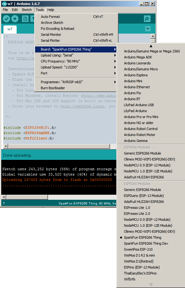
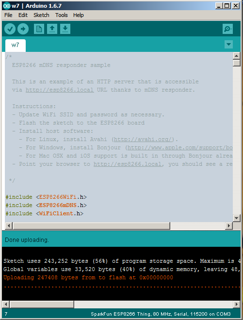
Flashing ESP8266 module with XTCOM_UTILITY:

Run the program and go to Tools->Config device. Select the Com port of FTDI adapter (only Com ports COM1-COM6 are supported - change port in Windows control panel if necessary). The port used by FTDI adapter is visible in Device Manager. In my case the port was COM2 and the speed was set to 115200. Press Open button to open the COM port and then click Connect.


Go to API TEST->Flash Image Download. Press Browse to select the firmware image and then press the Download button to start flashing.


Flash image file info output when using AT+GMR command:
AT version:0.21.0.0
SDK version:0.9.5


References: tutorial from iot-playground.com, images from stak.com and arduino-info.wikispaces.com
Similar tutorial: developer.mbed.org