8x8 dot matrix font generator for LCD

This is a javascript based 8x8 pixel font generator for any LCD.

How it works: just click on the dot matrix to enable and disable a dot. On the right side, the equivalent binary code will be generated. The reset button will reset the entire dot matrix. Multiple dot selection is not supported.

 0  0  0  0  0  0  0  0
 0  0  0  0  0  0  0  0
 0  0  0  0  0  0  0  0
 0  0  0  0  0  0  0  0
 0  0  0  0  0  0  0  0
 0  0  0  0  0  0  0  0
 0  0  0  0  0  0  0  0
 0  0  0  0  0  0  0  0

Binary code:


The code for generating "8x8 dot matrix font generator" is taken from www.pial.net.

QVGA 2.2" (240x320) TFT SPI display with SD-CARD pinout

The QVGA 2.2" TFT SPI display was bought from Ebay. The display driver is ILI9341 and the board uses 3.3V logic.
The maximum color depth this TFT supports is 16 bit.
The SD-CARD is powered from the display VCC and has separate SPI pins.

Warning! The QVGA 2.2" TFT does not support 5V on either of its pins.


The TFT display pins:

SDO (MISO)
LED = 3.3V or in series with a 100 ohm resistor from 5V
SCK (CLOCK)
SDI (MOSI)
D/C (DATA/COMMAND)
RESET
CS (CHIPSELECT)
GND
VCC = 3.3V

The SD-CARD pins:
SD_CS (CHIPSELECT)
SD_MOSI (MOSI)
SD_MISO (MISO)
SD_SCK (CLOCK)


References: ILI9341 PDF manual, www.instructables.com

PHP script to transform a 24 bits color depth image into 16 bits color depth raw and back again

Just like the title says, the following script will transform a 24 bits color depth image file into 16 bits color depth raw file. You also have the option to view that raw file.

Alternate link

16 bits RGB color representation

On a screen, each pixel is represented using 16 bits or 2 bytes (1 bytes = 8 bits). Each color has 5 bits allocated to its color depth, but green, which has 6 bits of color depth. This is the RGB565 format.


This can lead to small discrepancies in encoding, when someone wishes to encode the 24-bit color RGB with 16 bits. Green is usually chosen for the extra bit in 16 bits because the human eye has its highest sensitivity for green shades, therefore the discrepancies are harder to see. Note that 16 bits of color utilizes a color palette of 32x64x32 = 65,536 colors.

A few examples of 16 bits colors in C++:

Alternate link

References:
www.willamette.edu/~gorr/, wikipedia.org, learn.adafruit.com

Low voltage RS232/Serial switch

This schematic is useful when you have 2 devices that needs to be controlled by 1 MCU. As it's seen below, the MCU switches between the 2 serial devices. The MCU can only talk with 1 device at a time with both RX/TX channels.


SW1 can also be controlled by the MCU. U1 is 74HC04 or equivalent. U2 is SN74LVC125A or equivalent.

Reference:
WizFi250 Datasheet v1.01
PDF manuals:
Texas Instruments SN74LVC125A, NXP 74HC04

ESP8266 module family (versions)

At the moment of writing this note, ESP8266 had 14 versions in the family.

ESP-01

ESP-02

ESP-03

ESP-04

ESP-05

ESP-06


ESP-07

ESP-08

ESP-09
ESP-10

ESP-11

ESP-12

ESP-13
ESP-14

ESP boards summary table

Board ID pins pitch form factor LEDs Antenna Ant.Socket Shielded dimensions mm
ESP-01 8 .1" 2×4 DIL Yes Etched-on PCB No No 14.3 x 24.8
ESP-02 8 .1” 2×4 notch No? None Yes No 14.2 x 14.2
ESP-03 14 2mm 2×7 notch No CeramicNo No 17.3 x 12.1
ESP-04 14 2mm 2×4 notch No? None No No 14.7 x 12.1
ESP-05 5 .1" 1×5 SIL No None Yes No 14.2 x 14.2
ESP-06 12+GND misc 4×3 dice No None No Yes 16.3 x 13.1
ESP-07 16 2mm 2×8 pinhole Yes Ceramic Yes Yes 20.0 x 16.0
ESP-08 14 2mm 2×7 notch No None No Yes 17.0 x 16.0
ESP-08 New 16 2mm 2×8 notch No None No Yes 18.0 x 16.0
ESP-09 12+GND misc 4×3 dice No None No No 10.0 x 10.0
ESP-10 5 2mmm? 1×5 notch No None No No 14.2 x 10.0
ESP-11 8 1.27mm1×8 pinhole No? Ceramic No No 17.3 x 12.1
ESP-12 16 2mm 2×8 notch Yes Etched-on PCB No Yes 24.0 x 16.0
ESP-12-E 22 2mm 2×8 notch Yes Etched-on PCB No Yes 24.0 x 16.0
ESP-13 18 1.5mm 2×9 ? Etched-on PCB No Yes ? x ?
ESP-14 22 2mm 2×8 + 6 1 Etched-on PCB No Yes 24.3 x 16.2
WROOM-02 18 1.5mm 2×9 No Etched on PCB No Yes 20.0 x 18.0
WT8266-S1 18 1.5mm 3×6 1 Etched on PCB No Yes 15.0 x 18.6

References: www.esp8266.com

Arduino 1.6.7 with ESP8266 support

Using Arduino 1.6.7 with ESP8266 support is easy as is with any Arduino supported boards.

Installation:

1 The Arduino 1.6.7 can be downloaded here. After the zip file has been extracted, go to File -> Preferences and paste http://arduino.esp8266.com/stable/package_esp8266com_index.json in the
Additional Boards Manager URLs input. Click OK and go to Tools -> Board -> Board Manager... and search for ESP8266. The should be a esp8266 by ESP8266 Community package. I have installed the version 2.1.0 of that package.

The supported boards for this version are: Generic ESP8266 Module, Olimex MOD-WIFI-ESP8266(-DEV), NodeMCU 0.9 (ESP-12 Module), NodeMCU 1.0 (ESP-12E Module), Adafruit HUZZAH ESP8266 (ESP-12), ESPresso Lite 1.0, ESPresso Lite 2.0, SparkFun Thing, SweetPea ESP-210, WeMos D1, WeMos D1 mini, ESPino (ESP-12 Module), ESPino (WROOM-02 Module), WifInfo and ESPDuino.

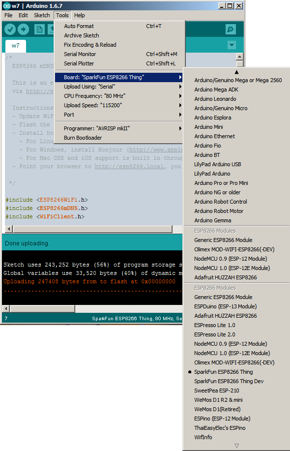
2 Now you can select the board from Tools -> Board -> Sparkfun ESP8266 Thing. The other settings can be seen in the screenshot below:


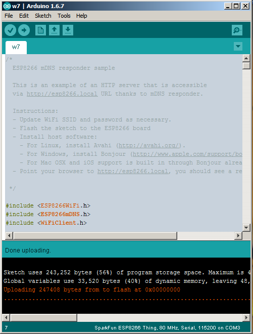
3 Now you can write your ESP8266 code and upload it. Upload complete on ESP8266 board messages:


Notes:
1. In order for this to function, you will have to flash ESP8266 with Arduino support firmware.
2. The software already contains several ESP8266 libraries, like: ESP8266WebServerESP8266 Multicast DNS and ESP8266WiFi.
References: esp8266.github.io, www.whatimade.today